Let’s put together the hardware that we purchased!
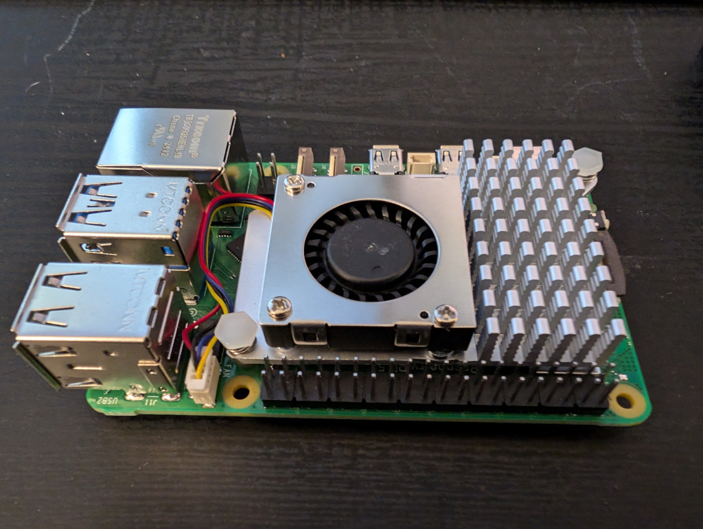
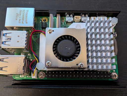
Step 1: Take out your Raspberry Pi 5!
Note that this Pi has the active cooler. This came from the kits I was buying. Without PoE I had to have the power bricks for each unit.
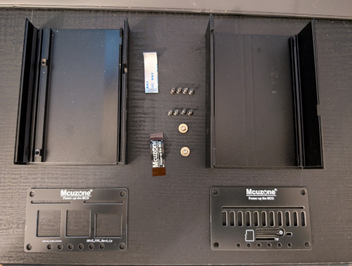
Step 2: Assemble the parts
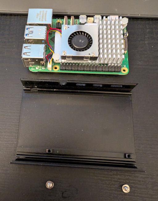
Here I layout the parts that came with the PoE+ hat, which included a case. I have to say, I really like this case. Even though the final cluster won’t be using this case, or this hat, or the Raspberry Pi 5, I intend to use these for the Pi 5s for other purposes.
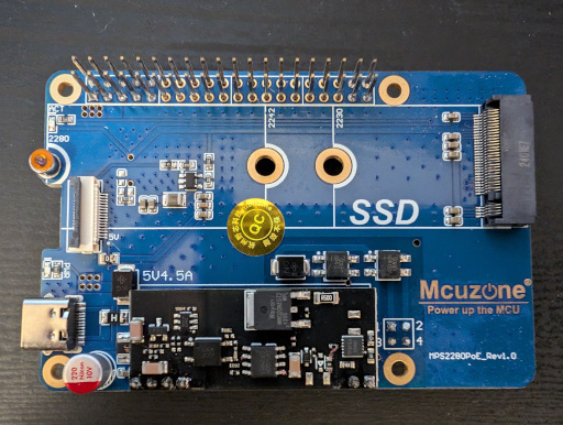
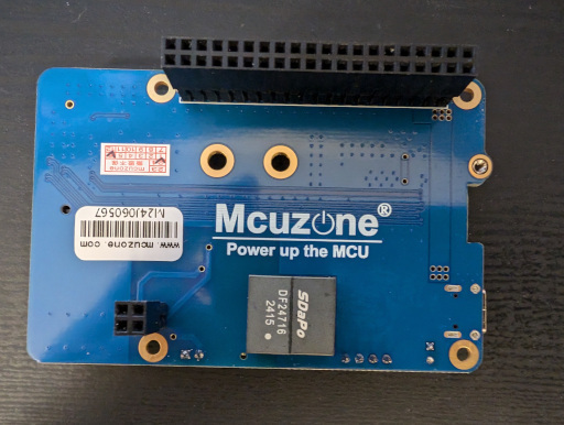
Here is the PoE hat itself.
Step 3: Mount the Raspberry Pi 5 into the case
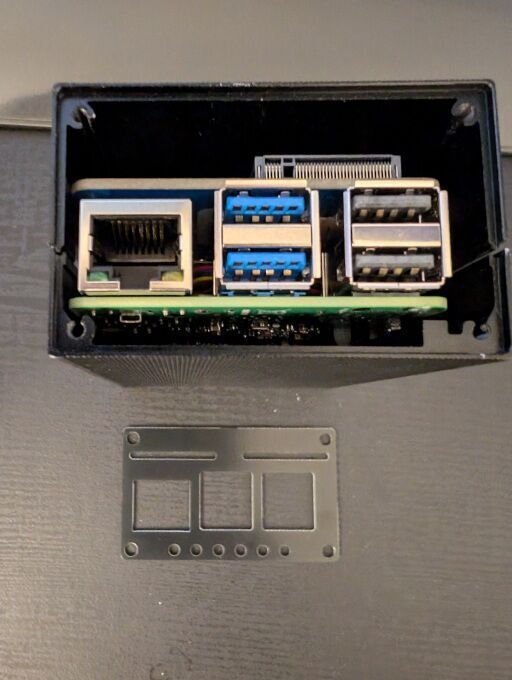
Don’t put that hat on too soon! The screws need to attach it to the aluminum bottom of the case. Here I show where the two screws will hold the Pi in place. The Pi will sit on the ledge on the opposite side so no screws are necessary.
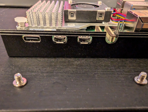
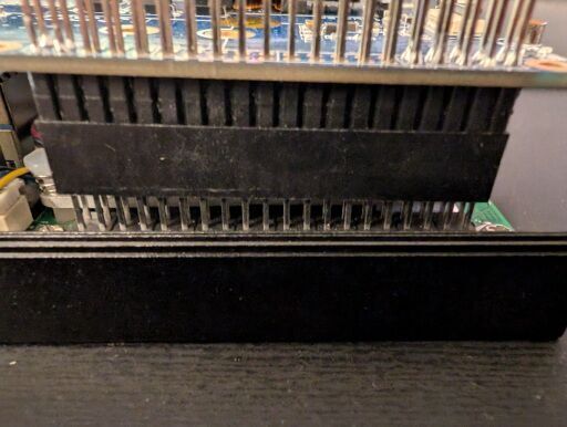
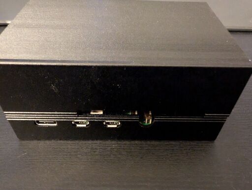
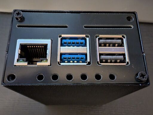
Here is what the ports side looks like.
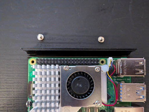
This is a top view of where the screws will be going.
Screw the screws into place. You don’t need to crank them down, just tight enough that they won’t come out.
Step 4: Insert the PoE hat onto the Raspberry Pi 5
The PoE hat will have the 40 pin GPIO and the 4 pin PoE connected it will fit on to. I find it’s easiest to focus on the 40 pin and make sure it’s fitted over the pins properly so that it isn’t offset in any direction. The 4 pin connector will naturally fit. Here is how the 40 pin looks when aligned.

Here is a view of the 4 pin when aligned.
Step 5: Install the PCIe ribbon
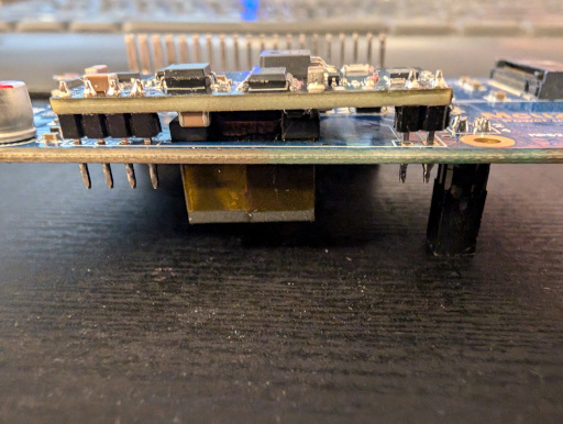
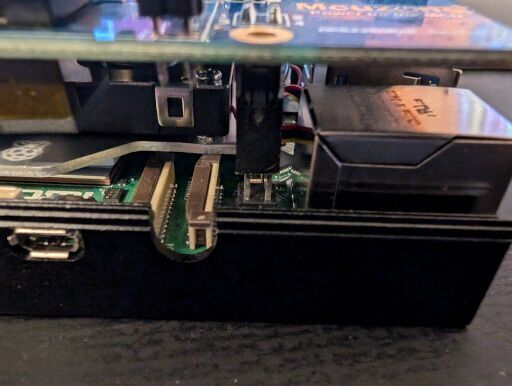
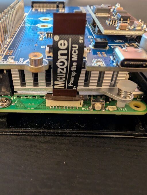
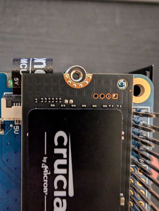
The deal with the PCIe ribbon is that it is like a sports car tire, it’s directional, in two cardinal directions. Ok, don’t let that discourage you because here is the trick, the ribbons are identified by a ‘1’ and in this case a ‘5v’ marker. All the ribbons I’ve installed have had their pins masked. In the below image you can see the ‘5v’ indicator as well as the brown that is making the pins. There is a corresponding ‘5v’ indicator on the PoE hat. From this image only the ‘v’ is visible as the ribbon connector is blocking it. We’ll get a better view of it in the next images. Ensure that the ‘5v’ indicators align.
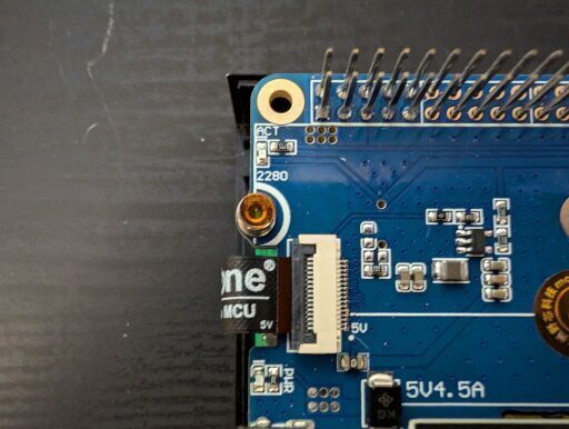
With very light force, we’re going to pull up on the lower brown, PCIe bracket up and ease the ribbon into the connector. Once in place with light force press each side of the brown, PCIe bracket down until it’s in place. It should look something like this.
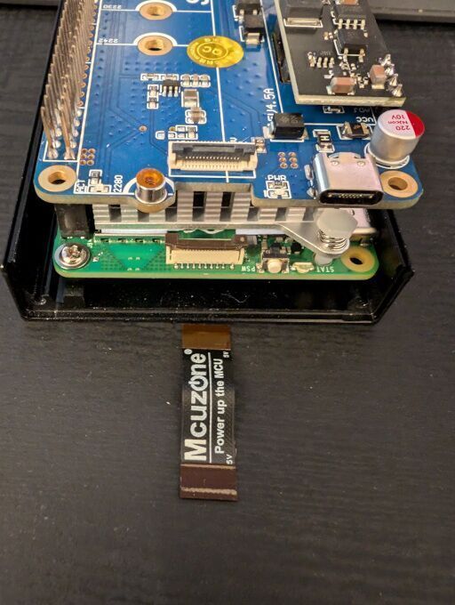
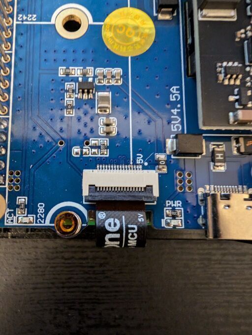
Next we will every so gently flip the upper black, PCIe bracket up and ease the ribbon into the connector. In this photo we can get a good look at the ‘5v’ indicator on both the ribbon and the PoE hat. It’s essential these line up to make the NVMe connector functional; so take a moment and reinsert the ribbon if necessary. Also please don’t ask me, or Giloveh, about my dyslexia, thank you. Once the PCIe ribbon is in place we will use that ever so gentle pressure to flip the black, PCIe bracket down, securing the ribbon in place. Once done it should look something like this.
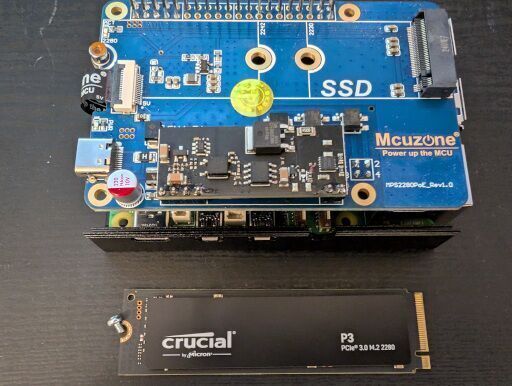
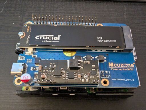
Step 6: Install the NVMe onto the hat
This step is straight forward, unless the sticker over the M.2 screw gaslights you for a minute or two. The NVMe SSD comes with a screw, which is what we will be using to secure it to the hat. Foreshadowing: In a future build we will discover that the screw is just to secure the drive into place and is otherwise not required.
Remove this sticker covering the NVMe screw hole and avoid the shame of not understanding why the screw won’t get purchase.
I didn’t show how the M.2 fits into the connector but there is a notch in the drive that will line up with the connector to avoid connecting it wrong. Align the drive to this notch and, optionally and it makes it easier at a roughly 45 degree angle, genitally insert the drive into the connector. Once inserted position the drive so that it is parallel to the hat and aligned to the screw as shown here.
Carefully screw the drive down only to a point that the screw and the drive stay put, don’t try to use any force. You should have something that looks like this.
Step 7: Screw in the screws for the case
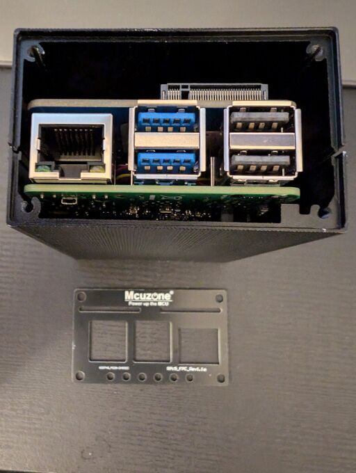
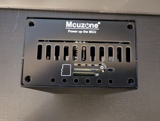
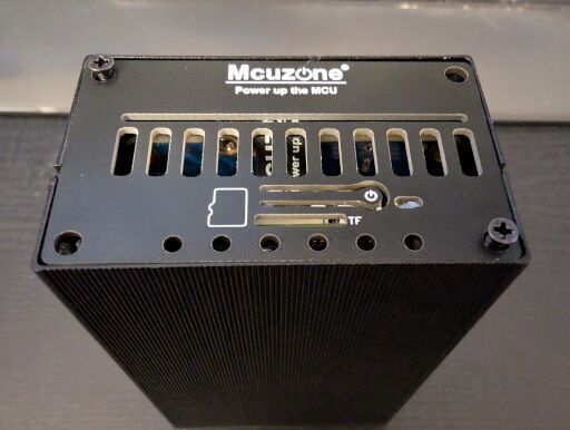
Here is where I will urge some caution. The case is really nice but the SD card slot will let you put the card in but not take it out. You wouldn’t believe how often I had to unscrew the case because I thought I had figured things out. That’s where something like this may come in handy. https://amzn.to/3zbLvnl – this is a small micro TF extender and it will extend the card out of the case. I didn’t purchase one, I don’t intend to purchase one and I intend to be done pulling the TF cards out of the Raspberry Pis. An alternative that I nearly did was take some tape and make a tab to pull the TF card out of the Pi. Ultimately I chose pain. Position the top of the case on so that the square hole for, I assume, camera ribbon cables to come out of, is over the ports like as such.
This next part shows that this case, not the PoE hat, was originally designed for the Raspberry Pi 4. The three squares don’t line up with the Raspberry Pi 5 because the 5 returned to the 3’s style with the ethernet on the side away from the GPIO pins. Do not panic! This is fine because the front pate is reversible; so you only have to face the silk screen side in.
Now screw the plate in. I did a crisscross install pattern but it was only to keep the top plate of the aluminum case from falling off.

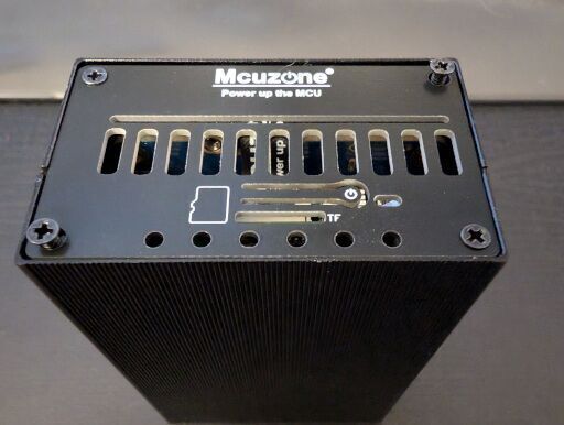
After the four screws on the USB/ethernet side of the Pi are secure we’ll do the other side much in the same way. This side is important to get right because that power button cut out needs to face in so that you can press the power button and so it will align with the TF card. Pictured is the side facing the camera which will point into the case.
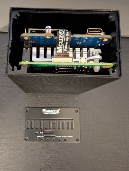
Not how there is a TF card logo that is facing out. This will also help orient the plate into the correct position.
Now we just need to install the screws. Again I follow a crisscross pattern but with the plate on the other side already installed, the only possible wonkiness is the case flexing apart. As I mentioned previously, you may want to solve the problem of getting at your TF card to reduce your stress. This could be just putting one or non screws in or creating the pull tab on the TF card with some tape as I mentioned above. If you do this, just make sure to not cover any of the TF card’s pins but enough coverage such that the tape doesn’t pull free. I have not do this, as I apparently like pain.
That concludes this tutorial for hardware version 2. There is a hardware version 3 we will be getting to soon; but before we get there, I’m going to cover some software basics to get the project up and running. These steps apply to hardware version 3 too, so it isn’t for nothing! Stay tuned for the next episode of the ARMada cluster project!
If there is any improvement to the documentation or pictures that you’d like to see, consider donating some energy drink money and saying what you’d like to see improved or if you’re happy with my work so far just leave an encouraging note! I can’t promise when I can get to it but it will help me prioritize my todos!
Leave a Reply